 Alt-i-ett COB LED-TV
 Fleksible LED-skjermer
 Gjennomsiktige LED-skjermer
 LED-plakat
 Sirkulære LED-skjermer
 LED-skjermer for kolonner
 Kreative og tilpassede LED-skjermer
New indoor wall
Start with the wall opening, viewing distance and required native pixels. The cabinet grid defines the complete display.
Discuss This InstallationLED Display with 320 × 160 mm Modules
A modular COB LED display for indoor walls and project-specific structures. Plan the cabinet grid, front-service access and electrical configuration around your installation.
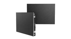
Each COB Beta cabinet holds six 320 × 160 mm modules in a 2-column × 3-row arrangement. The 4:3 cabinet format is a building block: the number of columns and rows determines the shape of the complete display.
The common-cathode design combines magnetic module mounting with front service. P1.25, P1.538 and P1.86 share the same standard cabinet and module dimensions, with different native pixel grids.
Start with the wall opening, viewing distance and required native pixels. The cabinet grid defines the complete display.
Discuss This InstallationCheck module positions, power, control capacity and service access against the current installation.
Discuss This InstallationDefine the display outline, fixing points and available depth before setting the module and support arrangement.
Discuss This Installation
Size presentation text and shared documents for the seating layout. Use the 640 × 480 mm cabinet grid to set the wall dimensions, then check native pixels, ambient light and front-service access.
Plan a Meeting-Room Wall
Review slides, diagrams and video from the nearest and furthest seats. Choose the pitch and cabinet layout together, with power, signal routes and maintenance access planned around the teaching space.
Plan a Teaching Display
Plan indoor brand displays around the available opening and visitor route. Check ambient light against the 600-nit specification, and review the supporting structure and connections for any custom outline.
Plan a Showroom DisplayCheck the opening, module dimensions, fixing positions and supporting-frame geometry. Include trim and front-service working space.
Review the module and cabinet electrical arrangement, available power, connectors and cable routing for the selected configuration.
Size the controller around the exact module pixel grid and complete display resolution. Retain the configuration records for maintenance.
Confirm front access, compatible spare modules and the replacement procedure. Keep wiring diagrams and the parts list with the installation.
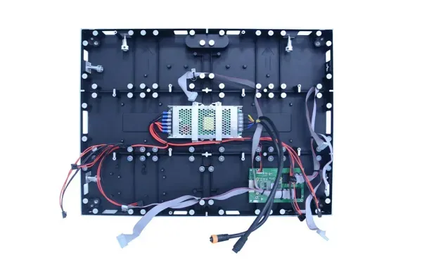
Four cabinet columns and three rows produce a 16:9 display. At P1.25, the native resolution is 2048 × 1152 pixels.
Calculated layout. Dimensions and weight exclude the support structure, trim and accessories.
Quote This Layout| Spesifikasjon | CB-I-P125 | CB-I-P153 | CB-I-P186 |
|---|---|---|---|
| Stigning (mm) | 1.25 | 1.538 | 1.86 |
| Pixel density (px/m²) | 640000 | 422500 | 288906 |
| Lysstyrke (nits) | 600 | 600 | 600 |
| Oppdateringsfrekvens (Hz) | 3840 | 3840 | 3840 |
| Module pixels | 256 × 128 | 208 × 104 | 172 × 86 |
| Kabinettpiksler | 512 × 384 | 416 × 312 | 344 × 258 |
| Gjennomsnittlig effekt (W/m²) | 100 | 100 | 100 |
| Maksimal effekt (W/m²) | 290 | 290 | 290 |
| Kontrollsystem | Novastar / Colorlight | Novastar / Colorlight | Novastar / Colorlight |
Equipment and document illustrations are references; your quotation and packing list define the supplied items and quantities.
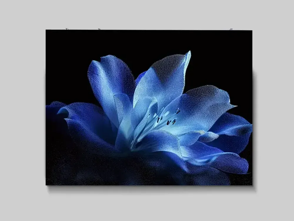
Standard cabinets measure 640 × 480 × 59 mm and weigh 7.5 kg each. The order specifies P1.25, P1.538 or P1.86, cabinet quantity and the complete wall layout.

Each standard cabinet contains six 320 × 160 mm modules in a 2 × 3 arrangement. Replacement modules must match the selected pitch and configuration; spare quantities are agreed in the quotation.
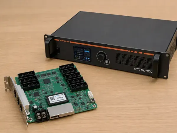
NovaStar or Colorlight equipment is specified around the complete wall’s native pixels and source requirements. Controller models, receiving equipment and quantities are identified in the order.
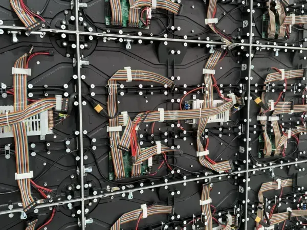
Mounting parts, power and signal cables follow the installation design. Existing structures are checked for fixing positions, electrical compatibility and front-service access before the scope is agreed.
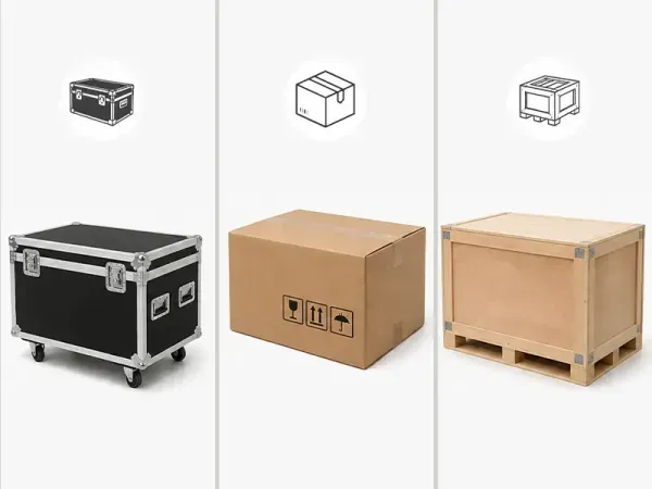
Packing type, quantities per package and delivery terms are agreed for the shipment. The packing list and order-specific packing photographs support the dispatch check.

Product and mounting drawings, wiring diagrams and installation instructions support the agreed configuration. Order-specific test videos, FAT records and spare-parts lists are available for handover.
Model specifications, cabinet pixels, power and control options.
Last ned databladProduct structure, layout examples and project-planning information.
COB Beta uses 320 × 160 mm modules in a 640 × 480 × 59 mm cabinet. Each cabinet contains two columns and three rows, for six modules in total. The specified cabinet weight is 7.5 kg. Mounting structure, cabling and accessories add to the complete installation weight and must be included when the supporting structure is designed.
COB Beta is available in P1.25, P1.538 and P1.86. Their module resolutions are 256 × 128, 208 × 104 and 172 × 86 pixels, respectively. Cabinet resolutions are 512 × 384, 416 × 312 and 344 × 258 pixels. Use these native pixel grids to size the complete wall and processor, alongside the required viewing distance and content.
Yes. Four cabinet columns and three cabinet rows form a 2.56 × 1.44 m display, which has a 16:9 aspect ratio. At P1.25, this layout uses 12 cabinets and 72 modules for 2048 × 1152 native pixels. A different target resolution requires a different grid. The active display dimensions do not include the mounting frame or finishing trim.
An existing structure can be evaluated for a COB Beta installation. The review needs the frame dimensions, module fixing positions, electrical connections, power provision, control equipment and maintenance access. A shared 320 × 160 mm footprint is only one part of that assessment. Send drawings or photographs and the current configuration so the module layout and any required adaptations can be established.
COB Beta uses magnetic module mounting and front service. Replacement work should follow the selected module and cabinet configuration, with matching spare modules and the correct electrical connections. Allow working space at the display face and retain the wiring and configuration records. The project handover can include the spare-parts list and installation instructions for the local maintenance team.
The order specifies the selected pitch, cabinet or module quantities, control equipment and installation accessories. Each standard 640 × 480 mm cabinet contains six 320 × 160 mm modules. Spare parts, packing and delivery terms are agreed in the quotation. Product and mounting drawings, wiring diagrams and installation instructions support the installation, with order-specific test records and packing photographs available for handover.
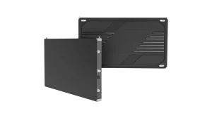
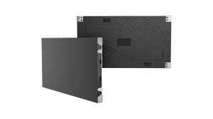
Share the wall dimensions or existing structure. We can review the module layout, connections and project scope.
En tegning, et bilde av byggeplassen eller en tidlig idé. Fortell oss hva du planlegger og jobb gjennom detaljene med vårt ingeniørteam.